
The Cais do Sodré shipwreck
Filipe Castro
Country: Portugal
Place: Lisbon, Cais do Sodré, under the subway station.
Coordinates: Lat. 38°42’21.44″N; Long. 9° 8’46.81″W
Type: Unknown, possibly a galleass.
Identified: No
Dated: Circa 1500 (C14)
Introduction
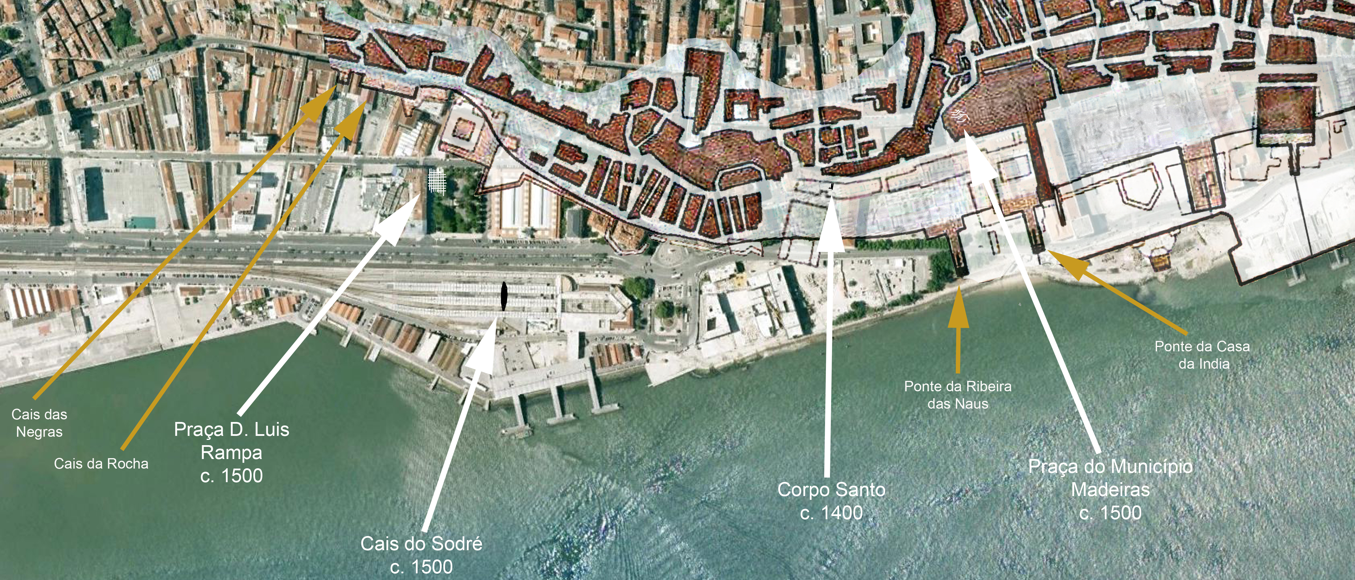
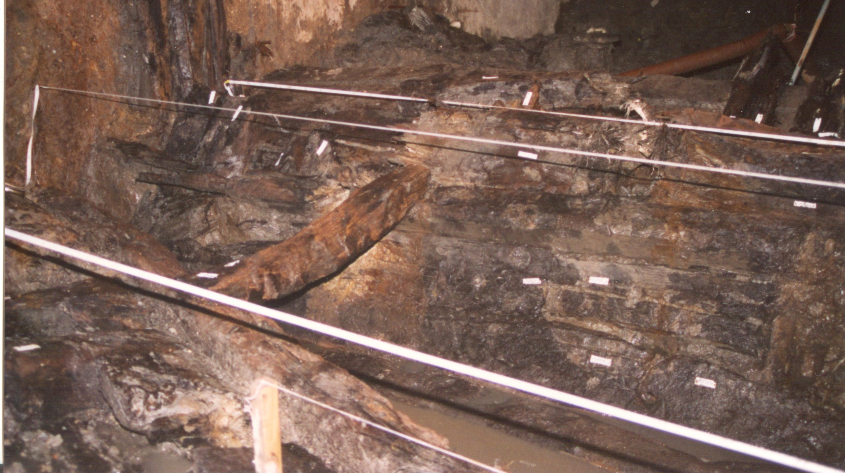
The Cais do Sodré shipwreck was found in April 1995 during excavation works for the construction of a new Cais do Sodré underground station near downtown Lisbon, Portugal. Unfortunately, nobody of the archaeological team was on the site when the digging machines hits the first timbers and the central portion, including the master frame(s), keelson and mast step were lost before the workers noticed the wooden structure, stopped the work and called the engineer in charge.
It is not clear whether this ship sank at a shallow depth and was subsequently salvaged, or whether it was abandoned.
Two lead sheathing fragments are mentioned in an internal memorandum dated 3 September 1996, together with a musket ball and a small collection of artefacts, bone fragments, and two sheave blocks, one of which was complete.
Since the artifacts were not positioned within the volume excavated (c.100 x 24 x 6.5 m) it is impossible to say whether they were associated with the ship remains.
The contractor decided to record the structure with a total station and moved a team to protect the surviving timbers and coordinate the work with the archaeological team.
A number of drawings were produced by the joint team and the present study is a reconstruction based on the data recorded during the hull excavation, disassembly and packing.
Team
The ship’s study was entrusted to archaeologist Paulo Jorge Rodrigues, who died untimely in November 2008, before its completion.
Story of the Ship
Nothing is known about the story of this ship. After the timbers were packed by the contractor and handed to the archaeological team the state agency abandoned the wet boxes to dry and the timbers warped and cracked before anybody took care of them.
Loss
As mentioned above, this ship was either salvaged or it is a derelict.
Table 1 – Radiocarbon dates of Cais do Sodré timbers.
| Date | Sample Reference | Sample Nature | Calibrated Date (2δ) |
| 1995 | Sac-1334 | Hull Plank | Cal AD 1424-1516 and 1590-1622 |
| 1995 | Sac-1335 | Floor Timber | Cal AD 1424-1516 and 1590-1622 |
| 2010 | Beta-279091 | Hull Plank | Cal AD 1520 to 1580* |
| 2010 | Beta-279090 | Floor Timber C148 | Cal AD 1420 to 1490 |
*And Cal AD 1630 to 1680, Cal AD 1770 to 1800, and AD 1940 to 1950
Find
The Cais do Sodré shipwreck was found in April 1995, during the excavation works for the construction of a new underground station near downtown Lisbon, Portugal, which is now the terminus of the line Caravela – named after this find.
Site Formation Process
The upper works degraded and disappeared and the bottom was lodged in the river bottom and preserved. In the mid-19th century earthworks covered the shipwreck area, when the waterfront was pushed outwards to allow the construction of the marginal avenue and the railway, which runs parallel to the coastline.
The construction of the “Caravela” subway station, located under the water table, entailed the excavation of the outer walls, which severed the hull’s bow and stern, and their construction in reinforced concrete. It seems that the presence of a ship’s hull was not noticed at this time. The second phase of the construction consisted of the injection of high-pressure concrete to create the bottom slab. The numerous circular holes in the Cais do Sodre structure resulted from the insertion of the injecting tubes.
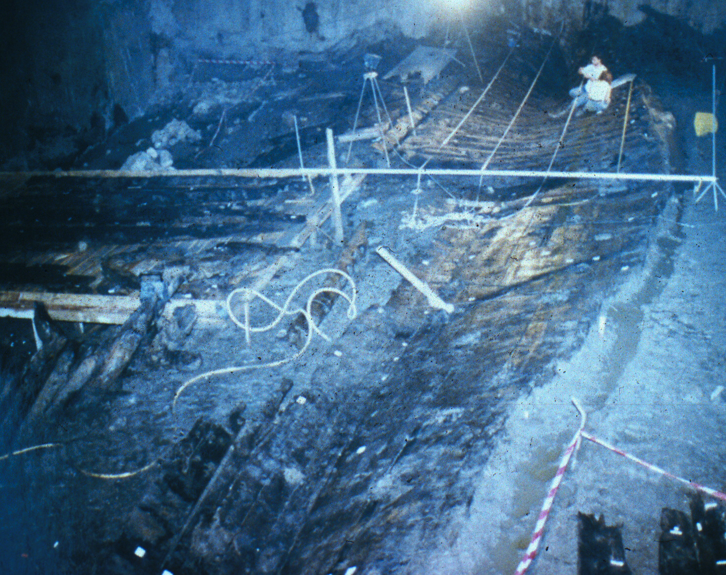
As mentioned above, the hull was detected during the excavation of the box contained in the bottom slab and outer walls. It happened in the middle of the night, when the archaeologist in charge of the supervision was not present, and the operator of the excavation equipment did not notice the wooden structure immediately and destroyed the central frames and mast-step. When the engineer was called to the site, the work was stopped, and a team of workers with a total station assigned by the contractor to record the find. the mast step and ventral frames had already been sent to the garbage dump and were not recovered by the services of the Ministry of Culture.
This ship was recorded and disassembled by the contractor, and the timbers boxed in wet mud and sent to the services of the Ministry of Culture, where they were abandoned to dry and warp for a number of months, as already mentioned.
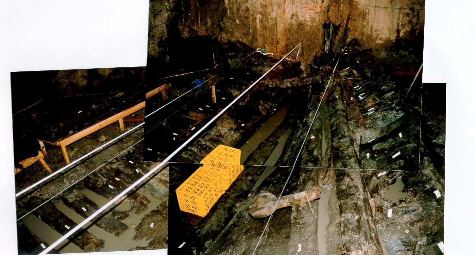
Tumulus
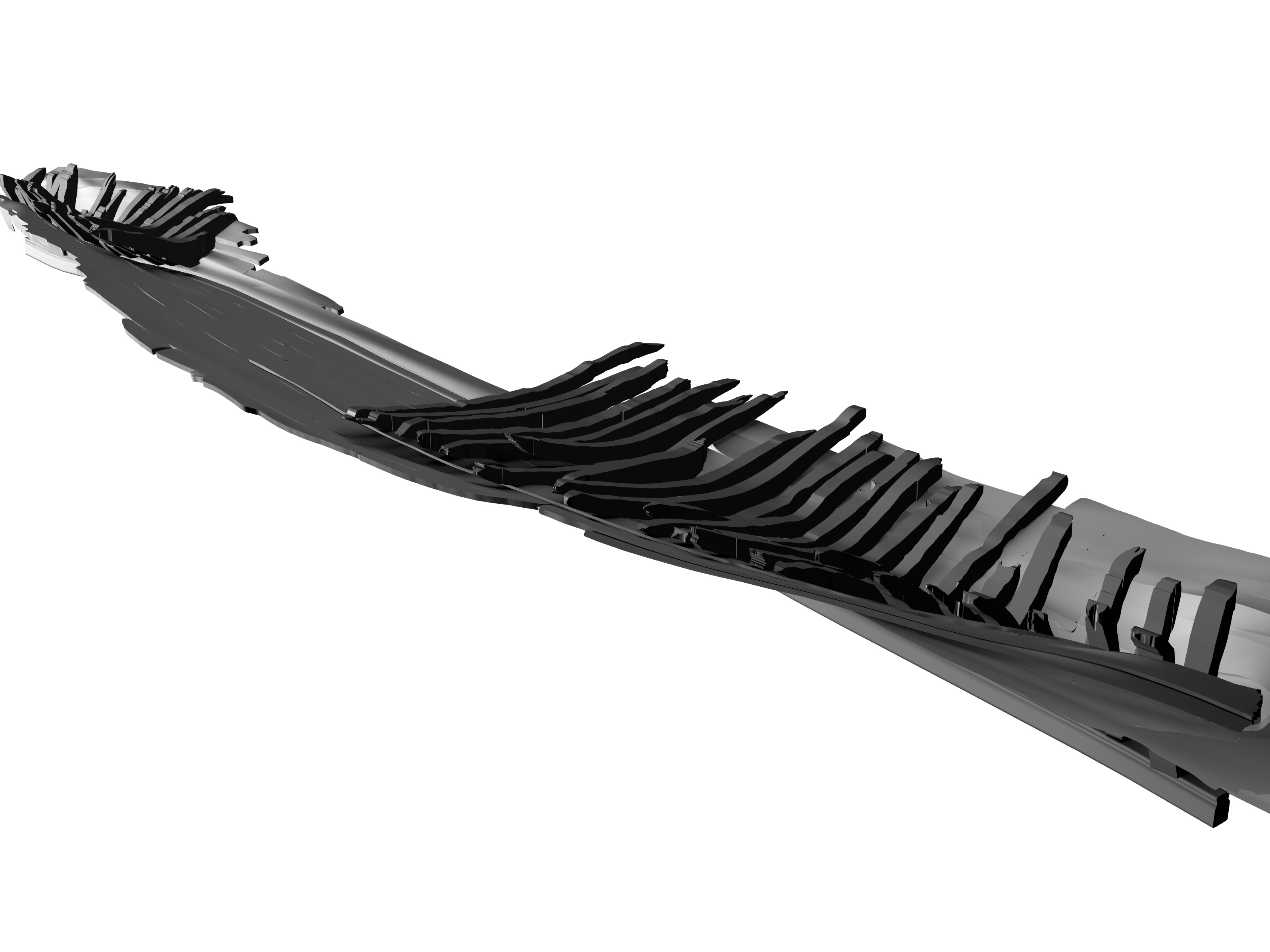
The Cais do Sodré shipwreck was found lying approximately in a north-south direction, with its presumed bow pointing to the north. The preserved remains consisted of a section of the keel almost 24 m long, fragments of 37 frames, one apron, part of the keelson, two stringers, some ceiling planking, one breast hook, one orlop beam, one maststep buttress, and one fragment of a stanchion. The hull planking was preserved along the full length of the shipwreck, with a maximum preserved width of about 4.90 m, and encompassing seven strakes to starboard and nine to port side.
Two stringers, one breast hook and nine strakes of ceiling planking, five to port side and four to starboard, were still in place, as well as the stomp of the stanchion mentioned above, with its tenon in place in a mortise carved on the upper face of the keelson.
As already mentioned, the bow and stern portions were cut during the excavation of the outer walls.
Ballast
There was no ballast.
Ship Fittings
Two rigging blocks are mentioned, and the bottom portion of a whipstaff.
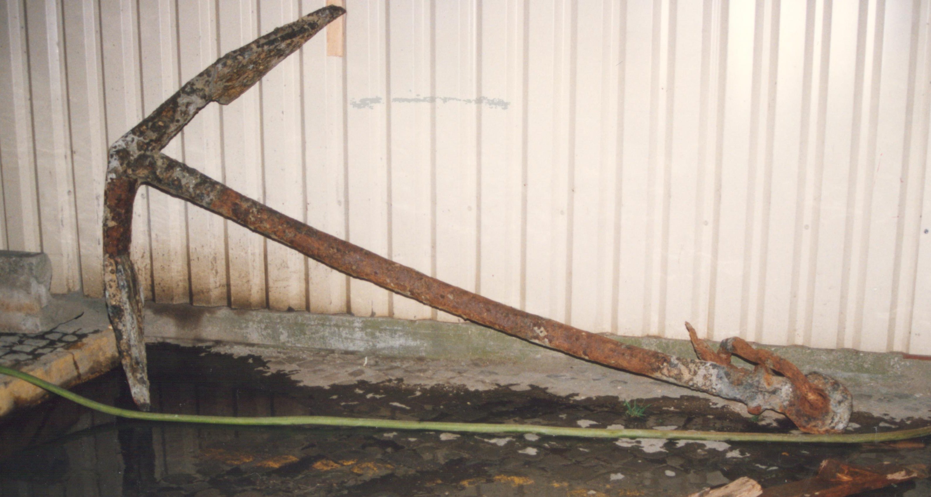
Anchors
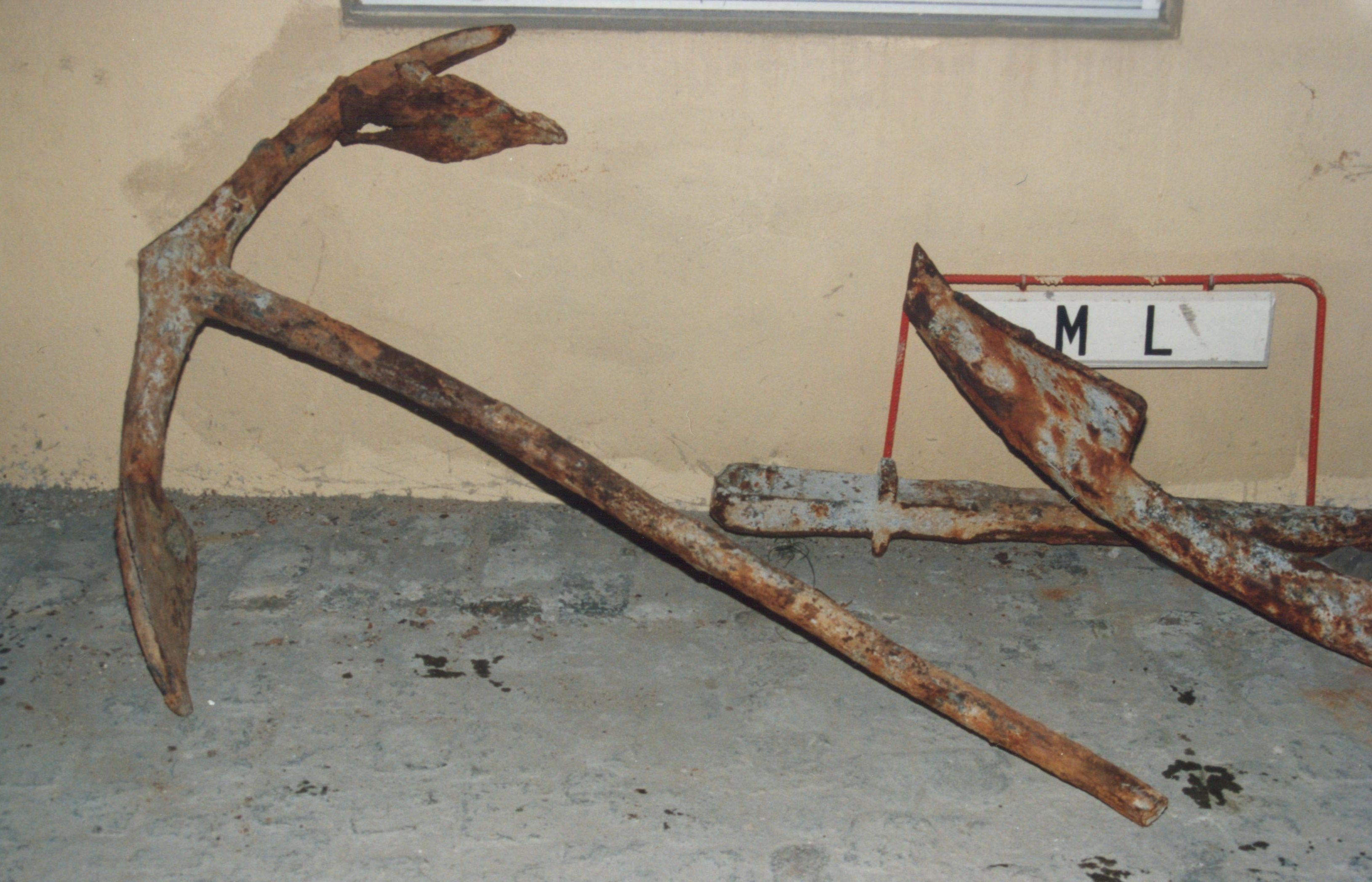
At least two anchors were found in the area, although it is impossible to say if they were related to the shipwreck (Fig. 4).
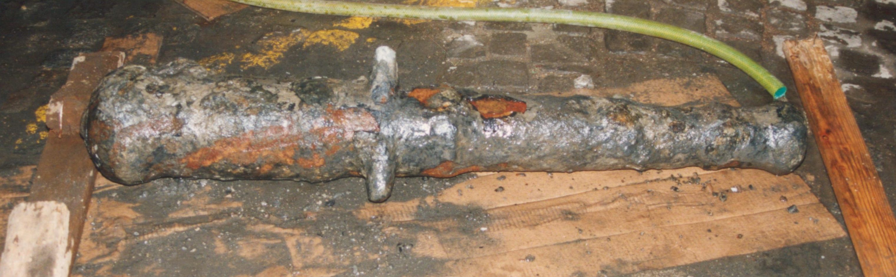
Guns
One small iron gun was found as well, but again it is impossible to say if it was part of this shipwreck (Fig. 5).
Other
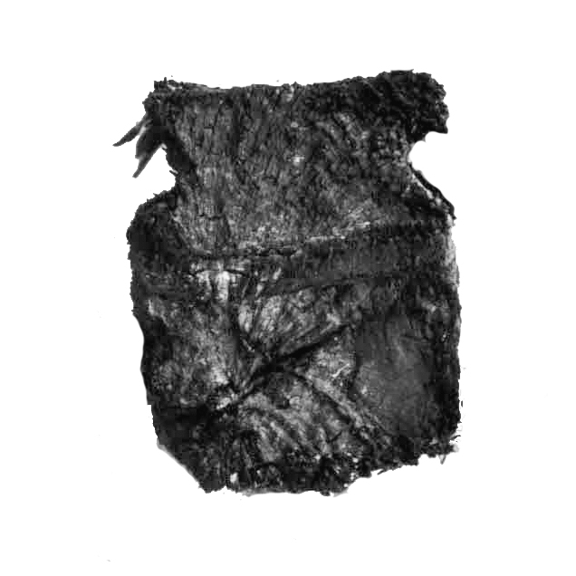
A shoe sole and a small number of other finds is mentioned in internal memos, but it is difficult to say whether they were conserved and studied.
Hull Remains (from the IJNA publication)
Scantlings
The timber scantlings are presented below:
Table 2 – Scantlings of the Cais do Sodré shipwreck: ceiling.
| Strakes
|
Ref. | Length
[m] |
Sided
[cm] |
Thickness
[cm] |
Wood species |
| North – Bow: Port side | |||||
| Strake 1 | O1.1N | 2.00 | 38 | 4-5 | Quercus faginea |
| O1.2N | 1.32 | 24 | 4-5 | Quercus faginea | |
| Strake 2 | O2.1N | 3.30 | 30 | 4-5 | Quercus faginea |
| North – Bow: Starboard | |||||
| Strake 1 | E1.1N | 2.84 | 15 | 4-5 | Quercus faginea |
| Strake 2 | E2.1N | 1.16 | 18 | 4-5 | Quercus faginea |
| South – Stern: Port side | |||||
| Strake 1 | O1.1S | 1.82 | 17 | 4-5 | Quercus faginea |
| O1.2S | 4.52 | 27 | 4-5 | Quercus faginea | |
| Strake 2 | O2.1S | 4.52 | 28 | 4-5 | Quercus faginea |
| O2.2S | 0.44 | 32 | 4-5 | Quercus faginea | |
| Strake 3 | O3.1S | 4.60 | 32 | 4-5 | Quercus faginea |
| O3.2S | 2.74 | 48 | 4-5 | Quercus faginea | |
| Strake 4 | O4.1S | 0.70 | 8-10 | 4-5 | Pinus pinea |
| O4.2S | 3.64 | 10-16 | 4-5 | Pinus pinea | |
| O4.3S | 2.76 | 20 | 4-5 | Pinus pinea | |
| O4.4S | 2.00 | 20 | 4-5 | Pinus pinea | |
| Strake 5 | O5.1S | 1.70 | 15 | 4-5 | Quercus faginea |
| O5.2S | 1.38 | 10 | 4-5 | Quercus faginea | |
| O5.3S | 1.02 | 10 | 4-5 | Quercus faginea | |
| O5.4S | 1.90 | 28 | 4-5 | Quercus faginea | |
| South – Stern: Starboard | |||||
| Strake 1 | E1.1S | 5.18 | 16-20 | 4-5 | Quercus faginea |
| Strake 2 | E2.1S | 1.54 | 16-20 | 4-5 | Quercus faginea |
| E2.2S | 5.16 | 18-24 | 4-5 | Quercus faginea | |
| Strake 3 | E3.1S | 1.40 | 18 | 4-5 | Quercus faginea |
| E3.2S | 5.14 | 24 | 4-5 | Quercus faginea | |
| Strake 4 | E4.1S | 1.56 | 12 | 4-5 | Pinus sylvestris |
Table 3 – Scantlings of the Cais do Sodré shipwreck: structural timbers.
| Timber | Ref. | Length
[m] |
Sided
[cm] |
Molded
[cm] |
Wood species |
| Keel | K1 | 8.48 | 25 | 27 | Quercus faginea |
| K2 | 3.39 | Quercus faginea | |||
| K3 | 7.57 | Quercus faginea | |||
| K4 | 2.97 | Quercus faginea | |||
| Keelson | KS1 | 1.30 | 27 | 26 | Quercus faginea |
| KS2 | 4.88 | Quercus faginea | |||
| KS3 | 2.60 | Quercus faginea | |||
| KS4 | 4.00 | Quercus faginea | |||
| Apron | A | 2.20 | 22.5 | 15 | Quercus faginea |
| 1st Stringer | SO1.1 | 2.80 | 18 | 17 | Quercus faginea |
| SO1.2 | 0.65 | Quercus faginea | |||
| SO1.3 | 8.75 | Quercus faginea | |||
| SE1.1 | 4.40 | Quercus faginea | |||
| 2nd Stringer | SO2.1 | 4.60 | 18 | 17 | Quercus faginea |
| SO2.2 | 4.80 | Quercus faginea | |||
| SE2.1 | 2.25 | Quercus faginea | |||
| Breast hook | B1 | 1.70 | 23 | 25-29 | Quercus rubor |
| Stanchion | St1 | 0.54 | 10 | 10 | Quercus faginea |
| Orlop beam | Ob1 | 1.16 | 18 | 18 | Quercus faginea |
| Buttress | Bt1 | 1.30 | 20 | 18 | Quercus faginea |
| Whipstaff | Ws | 0.75 | Ø 8 | – | Crataegus monogyna |
Table 4 – Scantlings of the Cais do Sodré shipwreck: hull planking.
| Strakes | Ref. | Length
[m] |
Sided
[cm] |
Thickness
[cm] |
Wood species |
| Starboard | |||||
| Strake 1 | TCE 1.1 | 5.45 | 22 | 7-8 | Quercus faginea |
| TCE 1.2 | 8.00 | 38 | 7-8 | Quercus faginea | |
| TCE 1.3 | 5.70 | 41 | 7-8 | Quercus faginea | |
| TCE 1.4 | 6.80 | 27 | 7-8 | Quercus faginea | |
| Strake 2 | TCE 2.1 | 6.25 | 35 | 7-8 | Quercus faginea |
| TCE 2.2 | 2.20 | 25 | 7-8 | Quercus faginea | |
| Strake 3 | TCE 2.3 | 0.95 | 43 | 7-8 | Quercus faginea |
| TCE 2.4 | 8.40 | 45 | 7-8 | Quercus faginea | |
| TCE 2.4a | 0.95 | 9 | 7-8 | Quercus faginea | |
| TCE 3.1 | 3.30 | 28 | 7-8 | Quercus faginea | |
| TCE 3.2 | 2.65 | 41 | 7-8 | Quercus faginea | |
| TCE 3.3 | 6.10 | 40 | 7-8 | Quercus faginea | |
| TCE 3.4 | 2.67 | 30 | 7-8 | Quercus faginea | |
| Stealer | TCE 3.5 | 3.40 | 19 | 7-8 | Quercus faginea |
| Strake 4 | TCE 4.1 | 4.35 | 15 | 7-8 | Quercus faginea |
| TCE 4.2 | 7.70 | 33 | 7-8 | Quercus faginea | |
| TCE 4.3 | 0.85 | 14 | 7-8 | Quercus faginea | |
| Strake 5 | TCE 5.1 | 1.17 | 20 | 7-8 | Quercus faginea |
| TCE 5.2 | 2.15 | 25 | 7-8 | Quercus faginea | |
| TCE 5.3 | 3.40 | 43 | 7-8 | Quercus faginea | |
| TCE 5.4 | 2.95 | 23 | 7-8 | Quercus faginea | |
| TCE 6.1 | 1.75 | 30 | 7-8 | Quercus faginea | |
| Strake 6 | TCE 6.2 | 3.35 | 35 | 7-8 | Quercus faginea |
| Strake 7 | TCE 7.1 | 1.15 | 21 | 7-8 | Quercus faginea |
| Port Side | |||||
| Strake 1 | TCO 1.1 | 11.20 | 30 | 7-8 | Quercus faginea |
| TCO 1.2 | 5.40 | 33 | 7-8 | Quercus faginea | |
| TCO 1.3 | 4.80 | 18 | 7-8 | Quercus faginea | |
| Strake 2 | TCO 2.1 | 9.30 | 45 | 7-8 | Quercus faginea |
| TCO 2.2 | 7.80 | 45 | 7-8 | Quercus faginea | |
| TCO 2.3 | 5.30 | 29 | 7-8 | Quercus faginea | |
| Strake 3 | TCO 3.1 | 16.50 | 39 | 7-8 | Quercus faginea |
| TCO 3.2 | 4.90 | 40 | 7-8 | Quercus faginea | |
| Repair | TCO 3.2a | 0.71 | 6 | 7-8 | Quercus faginea |
| TCO 3.3 | 1.70 | 15 | 7-8 | Quercus faginea | |
| Strake 4 | TCO 4.1 | 10.50 | 45 | 7-8 | Quercus faginea |
| TCO 4.2 | 12.80 | 52 | 7-8 | Quercus faginea | |
| TCO 4.2a | 2.08 | 25 | 7-8 | Quercus faginea | |
| Strake 5 | TCO 5.1 | 4.40 | 35 | 7-8 | Quercus faginea |
| Stealer | TCO 5.1a | 2.20 | 10 | 7-8 | Quercus faginea |
| TCO 5.2 | 6.20 | 22 | 7-8 | Quercus faginea | |
| Strake 6 | TCO 6.1 | 2.00 | 22 | 7-8 | Quercus faginea |
| TCO 6.2 | 8.75 | 48 | 7-8 | Quercus faginea | |
| TCO 6.2a | 2.20 | 8 | 7-8 | Quercus faginea | |
| TCO 6.3 | 8.70 | 39 | 7-8 | Quercus faginea | |
| Strake 7 | TCO 7.1 | 2.65 | 35 | 7-8 | Quercus faginea |
| TCO 7.2 | 1.15 | 30 | 7-8 | Quercus faginea | |
| TCO 7.3 | 11.55 | 32 | 7-8 | Quercus faginea | |
| TCO 7.4 | 2.00 | 33 | 7-8 | Quercus faginea | |
| Strake 8 | TCO 8.1 | 3.50 | 30 | 7-8 | Quercus faginea |
| TCO 8.2 | 2.50 | 27 | 7-8 | Quercus faginea | |
| Repair | TCO 8.2a | 0.52 | 14 | 7-8 | Quercus faginea |
| TCO 8.3 | 6.85 | 35 | 7-8 | Quercus faginea | |
| Strake 9 | TCO 9.1 | 6.25 | 20 | 7-8 | Quercus faginea |
Table 5 – Framing pattern: Filling floor timbers (South).
| Frame
No. |
Roman
Numeral |
Sided dimension | Space to the next frame | Height over the keel | Height 1 m from center |
| 77 | – | 19 | 17 | – | – |
| 78 | – | 20 | 43 | 47 | 18 |
| 79 | – | 18 | 28 | 36 | 15 |
| 80 | – | 21 | 24 | 34 | 16 |
| 81 | – | 20 | 24 | 37 | 17 |
| 82 | – | 21 | 21 | 36 | 18 |
| 83 | – | 24 | 25 | 41 | 17 |
| 84 | – | 23 | 24 | 39 | 16 |
| 85 | – | 18 | 19 | 38 | 17 |
Table 6 – Framing pattern: Pre-designed frames.
| Frame
No. |
Roman
Numeral |
Sided dimension | Space to the next frame | Height over the keel | Height 1 m from center |
| 86 | (I)IIVX | 21 | 21 | 40 | 19 |
| 87 | XVII* | 22 | 15 | 35 | 18 |
| 88 | IVX | 20 | 18 | 32 | 18 |
| 89 | XV* | 19 | 16 | 35 | 18 |
| 90 | IIIIX | 21 | 15 | 30 | 18 |
| 91 | XIII | 19 | 26 | 33 | 18 |
| 92 | XII | 18 | 19 | 34 | 21 |
| 93 | XI | 21 | 23 | 31 | 23 |
| 94 | Not visible | 19 | 18 | 31 | 19 |
| 95 | V(IIII) | 16 | 25 | 30 | 18 |
| 96 | VIII* | 19 | 22 | 31 | 19 |
| 97 | IIV | 21 | 15 | 30 | 19 |
| 98 | IV | 19 | 18 | 30 | 20 |
| 99 | V | 19 | 24 | 31 | 18 |
| 100 | II(I)I | 19 | – | 32 | 20 |
| Missing | III | – | – | – | – |
| Missing | II | – | – | – | – |
| Missing | I | – | – | – | – |
| Missing | MSF | – | – | – | – |
| Missing | I | – | – | – | – |
| Missing | II | – | – | – | – |
| Missing | III | – | – | – | – |
| Missing | IV | – | – | – | – |
| Missing | V | – | – | – | – |
| Missing | VI | – | – | – | – |
| Missing | VII | – | – | – | – |
| Missing | VIII | – | – | – | – |
| Missing | IX | – | – | – | – |
| Missing | X | – | – | – | – |
| Missing | XI | – | – | – | – |
| Missing | XII | – | – | – | – |
| Missing | XIII | – | – | – | – |
| Missing | XIV | – | – | – | – |
| Missing | XV | – | – | – | – |
| 140 | Not visible | 20 | 30 | 38 | 20 |
| 141 | IIV(X) | 20 | 11 | 38 | 20 |
| 142 | VXIII | 20 | 14 | 36 | 17 |
* Upside down
Table 7 – Framing pattern: Filling floor timbers (North).
| Frame
No. |
Roman
Numeral |
Sided dimension | Space to the next frame | Height over the keel | Height 1 m from center |
| 143 | – | 24 | 23 | 34 | 18 |
| 144 | – | 22 | 23 | 34 | 15 |
| 145 | – | 17 | 28 | 42 | 21 |
| 146 | – | 17 | 21 | 32 | 17 |
| 147 | – | 22 | 23 | 46 | 16 |
| 148 | – | 20 | 13 | 37 | 14 |
| 150 | – | 20 | 19 | 27 | 17 |
| 152 | – | 20 | 21 | 43 | 19 |
| 154 | – | 20 | 9 | 43* | 17 |
| 156 | – | 20 | 34 | 38* | 14 |
| 158 | – | 23 | – | 33* | 12 |
* Over the apron
Table 8 – Framing pattern: Pre-designed frames – Paulo Rodrigues coordinates.
| Frame
No. |
Roman
Numeral |
Horizontal line x | Horizontal line y | Vertical line x | Vertical line y |
| 86 | (I)IIVX | 117 | 60 | – | – |
| 87 | XVII* | 122/129 | 61/60 | 134 | 63 |
| 88 | IVX | 130 | 55 | – | – |
| 89 | XV* | – | – | – | – |
| 90 | IIIIX | 150 | 52 | 169 | 62 |
| 91 | XIII | 158 | 54 | 175 | 60 |
| 92 | XII | – | – | – | – |
| 93 | XI | – | – | – | – |
| 94 | Not visible | – | – | – | – |
| 95 | V(IIII) | 183 | 47 | – | – |
| 96 | VIII* | – | – | – | – |
| 97 | IIV | 198 | 44 | – | – |
| 98 | IV | – | – | – | – |
| 99 | V | 201 | 45 | 226 | 51 |
| 100 | II(I)I | 205 | 44 | 224 | 50 |
| Central 19 frames missing: 3 abaft, one master frame, and 15 forward | |||||
| 140 | Not visible | – | – | – | – |
| 141 | IIV(X) | – | – | – | – |
| 142 | VXIII | 107 | 65 | ||
* Upside down
Description
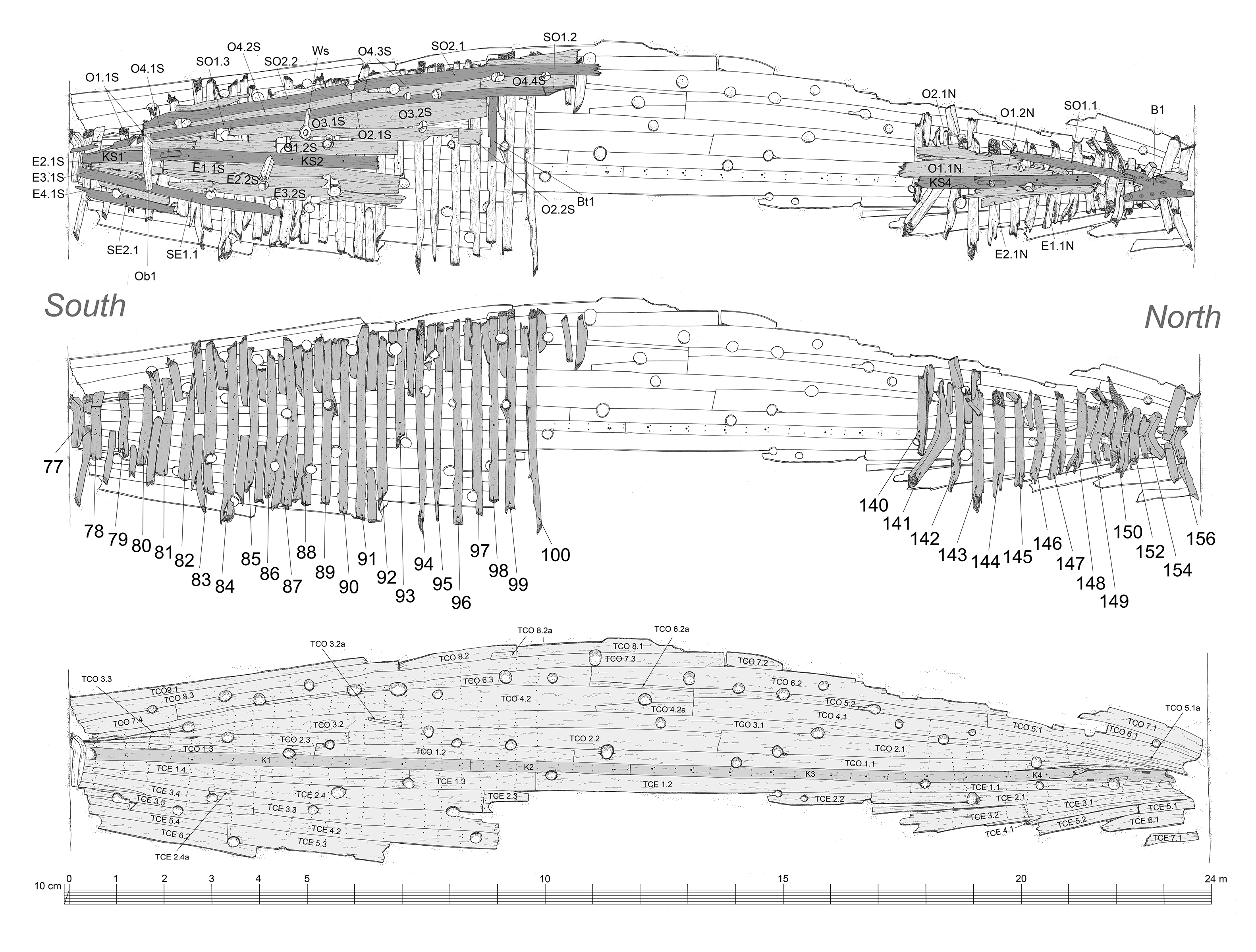
After a reanalysis of the primary data was carried out to clarify any existent doubts, new 1:10 drawings were produced, all timbers were numbered, referenced and measured. Sections of the hull spaced 1 m apart were drafted from the total station drawings, and a preliminary hull analysis was performed with the use of 3D software Rhinoceros®.
We based our analysis on Paulo Jorge’s drawings and notes and kept the timber designations every time when possible. Changes were made, however, upon clarification of certain details in the original drawings, and the resulting nomenclature is a mix of Portuguese and English initials (“O” and “E” stand for West and East, Oeste and Este in Portuguese, “TC” for tábua de casco, hull plank, and “S” for strake). The approximate dimensions of the timbers preserved are indicated on Tables 2 through 4.
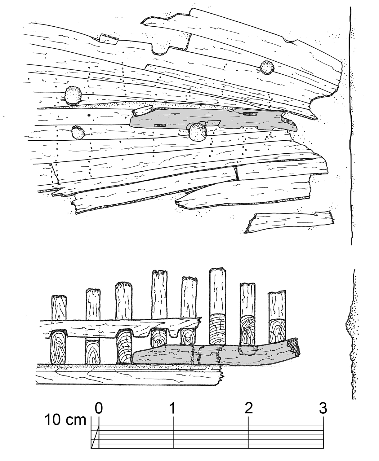
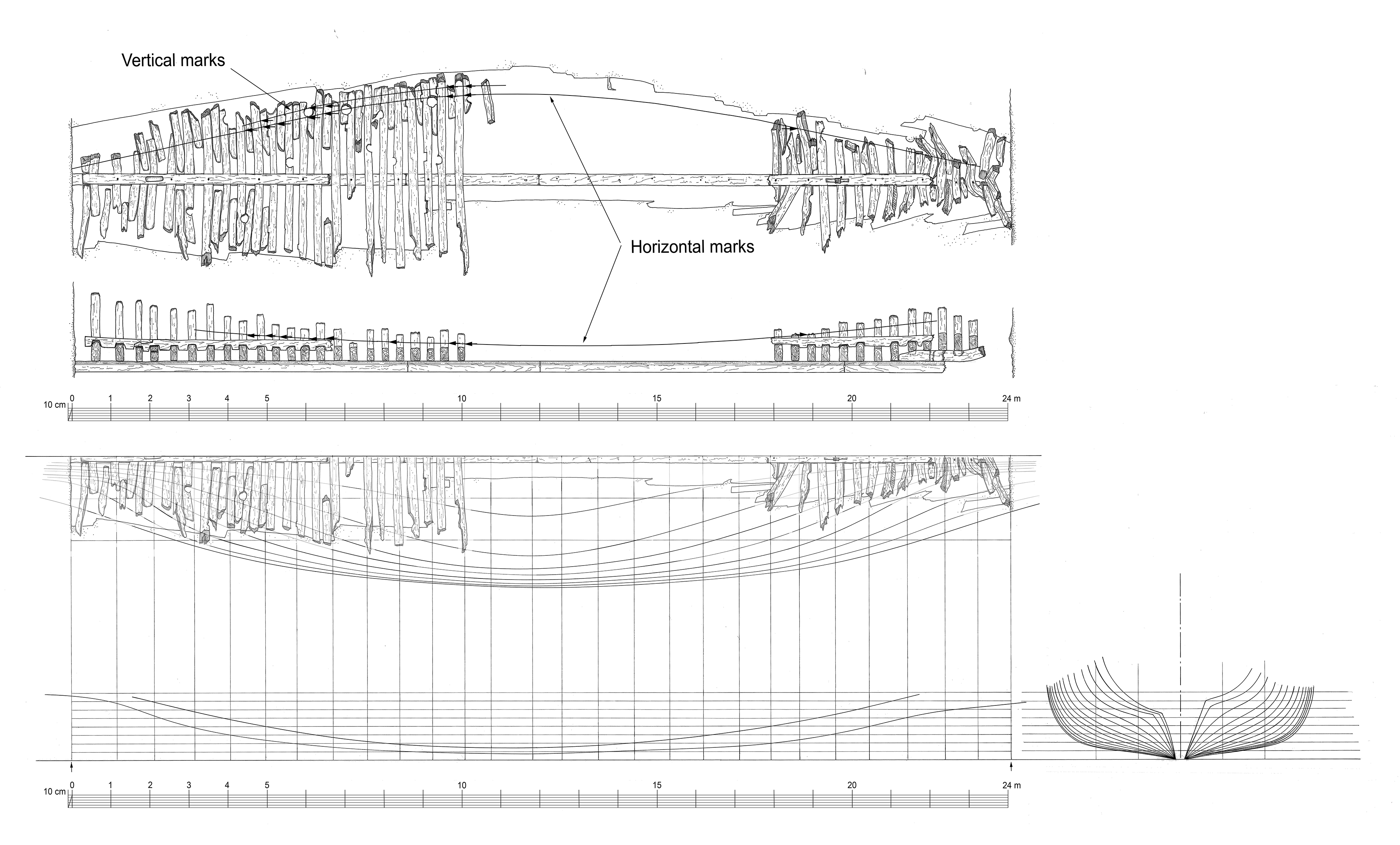
There is a substantial amount of evidence suggesting that this ship was constructed following a method common in the Mediterranean and the Iberian Peninsula, where the central frames are pre-designed and pre-erected, defining the shape of the central portion of the hull, and the ends are fashioned by eye using ribbands (armadouras). The central frames showed a number of interesting features, including construction marks engraved on the faces of some of the floor timbers.
The construction marks consisted of a sequential numbering of 18 frames on both sides of a single master frame, as a series of vertical lines, marking the edges – in Portuguese astilhas – of the keel, and two sets of lines in the zone of the turn of the bilge.
Since some of the excavation notes have not been found, some of the timber dimensions were taken from the 1:10 scale original drawings. There were doubts about the interpretation of some of these drawings, namely about what pertains to the total lengths of some of the hull planks, which at times seem implausibly long. Such are the cases of:
- Planks TCE 1.1 and TCE 1.2, the seam between them is not clearly indicated in the original;
- Plank TCO 3.1, which probably corresponds to two planks;
- Planks TCO 4.1, 4.2, and 7.3, implausibly long.
A second problem in the interpretation of the data is associated with the difficulty of finding the center plane of symmetry of each frame. Without this plane it is impossible to determine the coordinates of the construction marks.
Keel
The keel was preserved along almost the entire distance between the concrete walls of the subway station. It presented the same rectangular transversal section throughout the entire length, 25 cm sided and 27 cm molded. The ship’s bow and stern were cut in the excavation process and the ends of the hull were badly disturbed. At the bow, the keel was twisted to port side and the entire structure was incoherent near the wall. As indicated on Table 2, it was composed of four timbers of different lengths. Each section butted against the next without any scarf.
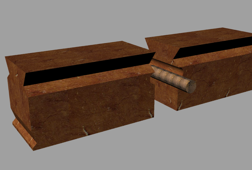
A water stop dowel was inserted under the rabbet line in all three preserved connections. This solution is illustrated in the anonymous text entitled Traité de Construction the Galères, which dates to the late 17th century (Rodrigues 2002, 15), but has no parallel in other published Iberian ships. A butt scarf was found on the connection of the Culip VI keel and stem post. The keel’s lower face showed signs of use, making it unlikely that there was ever a shoe underneath.
Apron
Part of an apron was preserved in the bow area, badly broken. It was 22.5 cm sided and 15 cm molded and the upper surface of its forward portion curved upwards with a radius of approximately 80 cm to 1 m.
The apron’s upper surface was notched on its sides to fit the feet of “V-shaped” frames. The notches were around 5 cm deep and 5 cm wide, and as long as the sided dimension of the frames they received.
The apron was bolted to the keel and possibly also to the stem post, although it’s upper section was not preserved. No drawings were made of this timber, but its curvature was reconstructed from the total station coordinates in the respective drawing. The longitudinal representation in Figure 10 below is conjectural, based on the data available for the timber’s upper surface.
Keelson
The keelson was partially torn apart by the bulldozer operator. Four sections were recorded, three on the site plan made with the total station, and the fourth later, in 1997, by the author. The keelson had a constant transversal section (27 cm sided x 26 cm molded) and was notched underneath, to fit over the floor timbers.
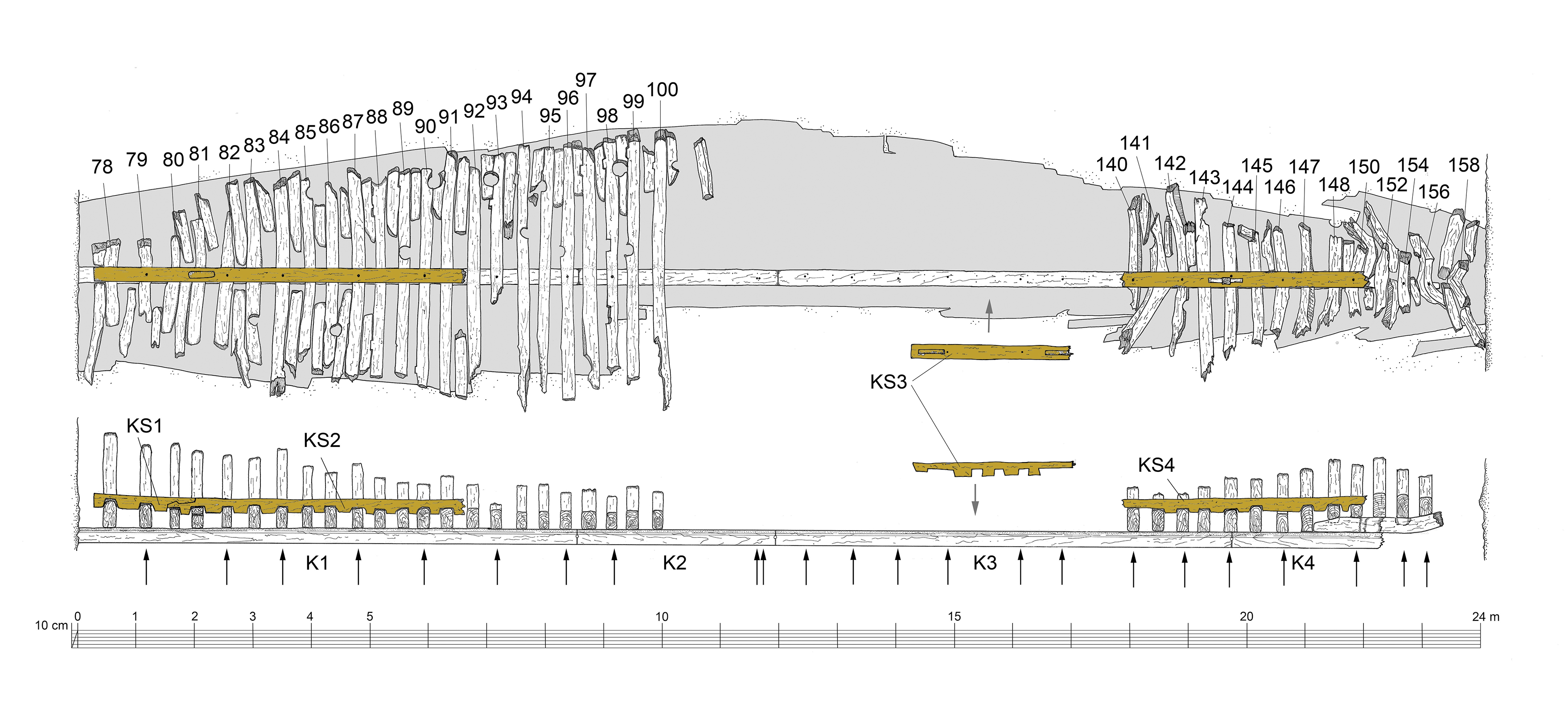
Fragments KS1 and KS2 were still in place and connected through a horizontal hooked scarf. Section KS3 was positioned during the reconstruction process by comparing the distances between fastening holes. The only possible position is indicated on Figure 11, although at this point it is impossible to establish whether its scarf was pointing to the bow or the stern of the vessel. The keelson was fastened to the keel with iron bolts presumably inserted from underneath, about 30 mm in diameter at irregular intervals, generally every other or every two frames.
Frames
A total of 43 frames were preserved, all in their original positions, 19 to the north, in the bow area, and 24 to the south, in the stern area. As mentioned above, each of the floor timbers was drafted at a 1:1 and a 1:10 scale in 2001 and 2002. The preserved frames fall into two clear categories: pre-designed frames (cavernas graminhadas) and filling floor timbers (enchimentos).
The pre-designed frames were composed of one floor timber and two futtocks, and were fastened to the keel with two iron spikes each, inserted through a recess cut on the forward face of the stern frames and on the aft face of the bow frames. Each futtock was fastened to the floor timber with a dovetail scarf and three iron spikes, always inserted from the floor timber side. The dovetails were always wider at the lower side, which measured between 17 and 31 cm. The dovetail tops measured between 11 and 23 cm. Dovetails were salient on all floor timbers except C93, where the only dovetail that survived, on port side, was recessed. Dovetail thicknesses varied between 1.5 and 2 cm, or around the value of the 16th century dedo (1.8 cm). Pre-designed frames were numbered with Roman numerals from I to XVIII before and after a single master frame, which was torn apart by the bulldozers and thrown away before the archaeologists became involved in the discovery of the shipwreck. The master frame was fastened to the keel with one iron spike and two iron bolts. As mentioned earlier, the pre-designed frames showed three types of construction marks:
- Two vertical lines marking the foot of the frame, where it sits on the keel. There are seldom vertical and often times do not allow us to clearly establish the design vertical axis of the frame;
- One or two horizontal lines (in some cases not horizontal at all) which allegedly marked the base of the mold from which all floor timbers seem to have been cut; and
- One or (possibly) two vertical marks near the turn of the bilge arc, to the outside of the horizontal line, in reality diagonal, whose significance is not clear at this point.
The filling timbers were fastened to the keel with a single iron spike, inserted in a recess cut for that purpose, and were not fastened to the respective futtocks. These timbers were not numbered. However, six timbers – numbers 80, 82, 83, 85, 150 and 152 – showed vestigial diagonal lines that may be related to the construction process. Timbers C78 and C81 had one arm scarved into their lower section, presumably for lack of suitable “Y-shaped” timbers.
Almost all floor timbers – C89 to C100, C140 to C145, and C148 – had one limber hole, positioned on the port side, between 20 and 45 cm from the central axis of the ship. Floor timbers C90 and C96 had two limber holes each.
The positions of the missing frames were not recorded based on the fastening marks of the hull planking at the time, but later Paulo Rodrigues made a 1:10 scale drawing of the upper face of keel section K2, and in July 2010 a team of students under the orientation of Francisco Alves made a 1:1 scale drawing of the upper face of keel section K3. From these drawings the positions of the missing frames were easily deduced, considering the clear fastening pattern observed on both drawings. The distances between fastening holes are indicated in Table 6, together with the sided and molded dimensions on each frame, the first measured in the more accurate total station drawing, and the second in the 1:10 drawings made by the Texas A&M teams in 2001 and 2002, from the dried and warped timbers. The scantlings presented below are therefore average values, measured on the dried timbers, after considerable radial shrinkage and warping occurred.
Room and space are indicated as measured in the total station drawings, which suggest that the distance between the concrete walls was not 24 m, but rather 23.95 m.
The positions of the construction marks were measured by Paulo Rodrigues on the dried and warped timbers. When measured again in the ShipLab, from the frames 1:10 drawings, there were a number of differences, always associated with the difficulty to establish their vertical axis. The values presented below are those measured by Paulo Rodrigues directly from the frames (Rodrigues 2002, 37). Further analysis has allowed us to refine these values and will presented in a future publication.
The futtocks were never recorded at a 1:1 scale, but as none was preserved beyond the tips of the floor timbers, this lack of data is not particularly important at this point.
Planking
The planking was 7 to 8 cm thick. All boards were cut from Portuguese oak (Quercus faginea), a tree rather common in the western Mediterranean, namely in the Iberian Peninsula and the north of Africa.
No caulking arrangement was reported during disassembly. It is unknown whether the two lead sheathing fragments mentioned in the 1996 memorandum were found in association with the hull planking, or whether there were any caulking remains between the planks.
Nine strakes of hull were preserved to port side and seven to starboard. Drop strakes and stealers were used to achieve the sharp dead rise at the bow and stern (Figure 4 and Table 4). Most planks were cut from large oaks, presenting a maximum length of around 8 m and average widths between 20 and 50 cm. Each plank was fastened to the frames with two spikes per frame and three near the hoods. Wider planks had 3 spikes per frame and four spikes near the hoods. A conversion study was not performed on the hull planks of the Cais do Sodré ship and at this point it is difficult to envision such a study, given the fact that most of the plank’s labels fell or are ineligible.
The garboards had the same thickness as the rest of the hull and were chamfered to fit the keel rabbets.
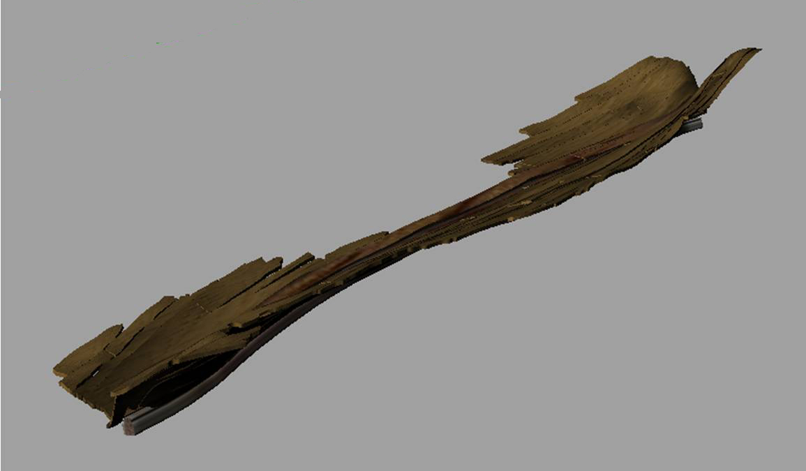
An analysis of the total station data showed that the hull was heavily hogged in its undisturbed condition and that the planking opened and sunk after the removal of the ceiling and framing.
Once we manage to reconstruct the hull shape to a plausible configuration, the extent to which the Cais do Sodré hull planking was preserved and recorded, this should allow an attempt to reconstruct the shape of the stern and stem posts, by extending each plank in a 3D model.
Ceiling
The ceiling planking was made of 4 to 5 cm boards of Portuguese oak (Quercus faginea) and preserved near the bow and the stern of the shipwreck. In the north or bow portion, only two strakes on each side survived that were too torn apart to allow a good analysis about its solidity. In the stern area the strakes were much better preserved – five strakes to port and four to starboard – and their condition suggested that it was carefully laid by good and competent carpenters. The maximum length of the surviving planks was above 4 m, and lengths varied between 10 and 48 cm.
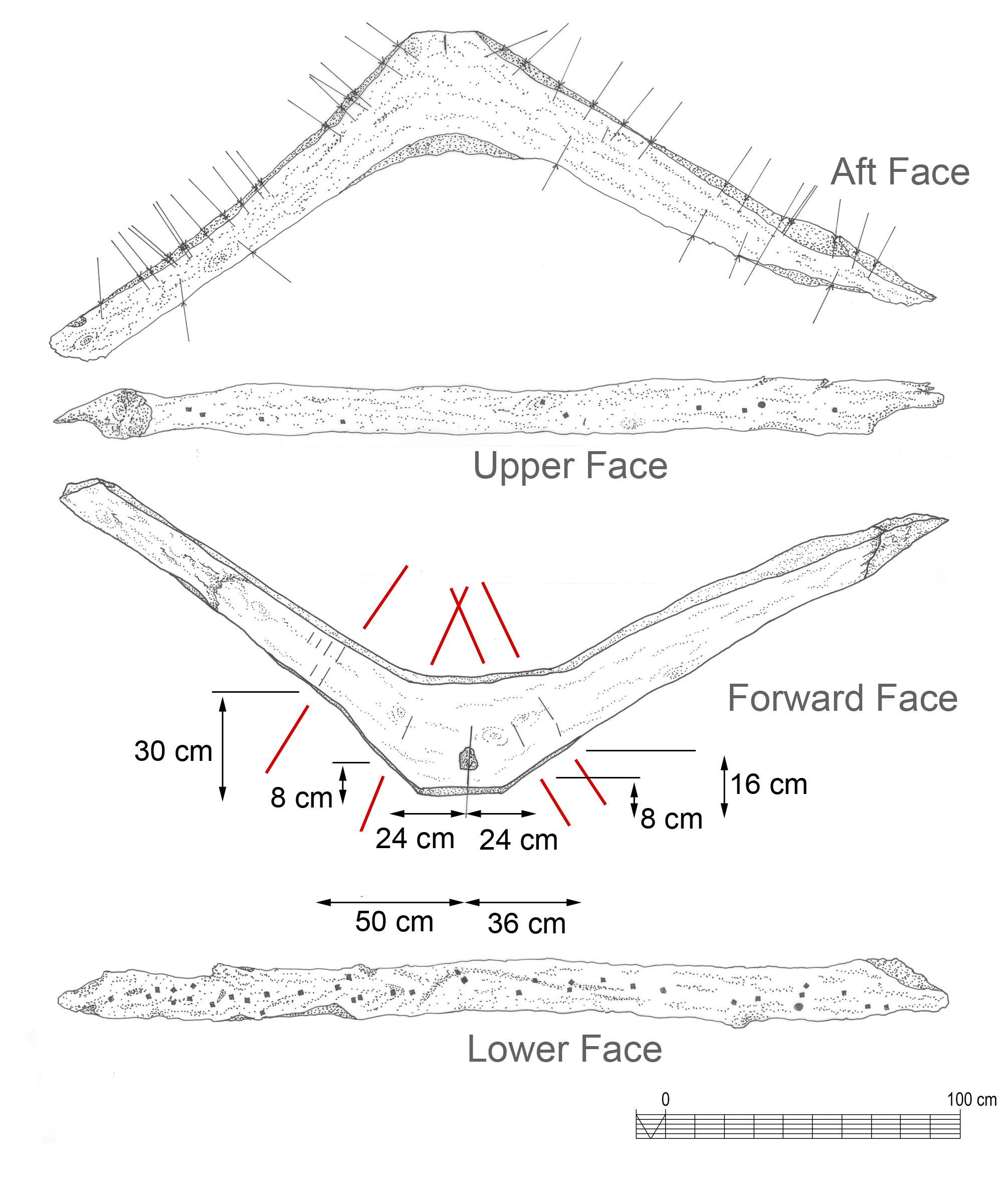
Breast Hook
One breast hook was preserved in the northern portion of the hull. It was the only timber preserved that was cut from an English Oak (Quercus robur).
The breast hook was roughly carved from a “Y-shaped” timber 1.7 m long, had a maximum sided dimension of 60 cm and molded dimensions that varied from 30 cm at the forward most section to 45 cm in the central zone. It connected to the lower stringers through flat hooked scarves about 42 cm long and was spiked to the frames.
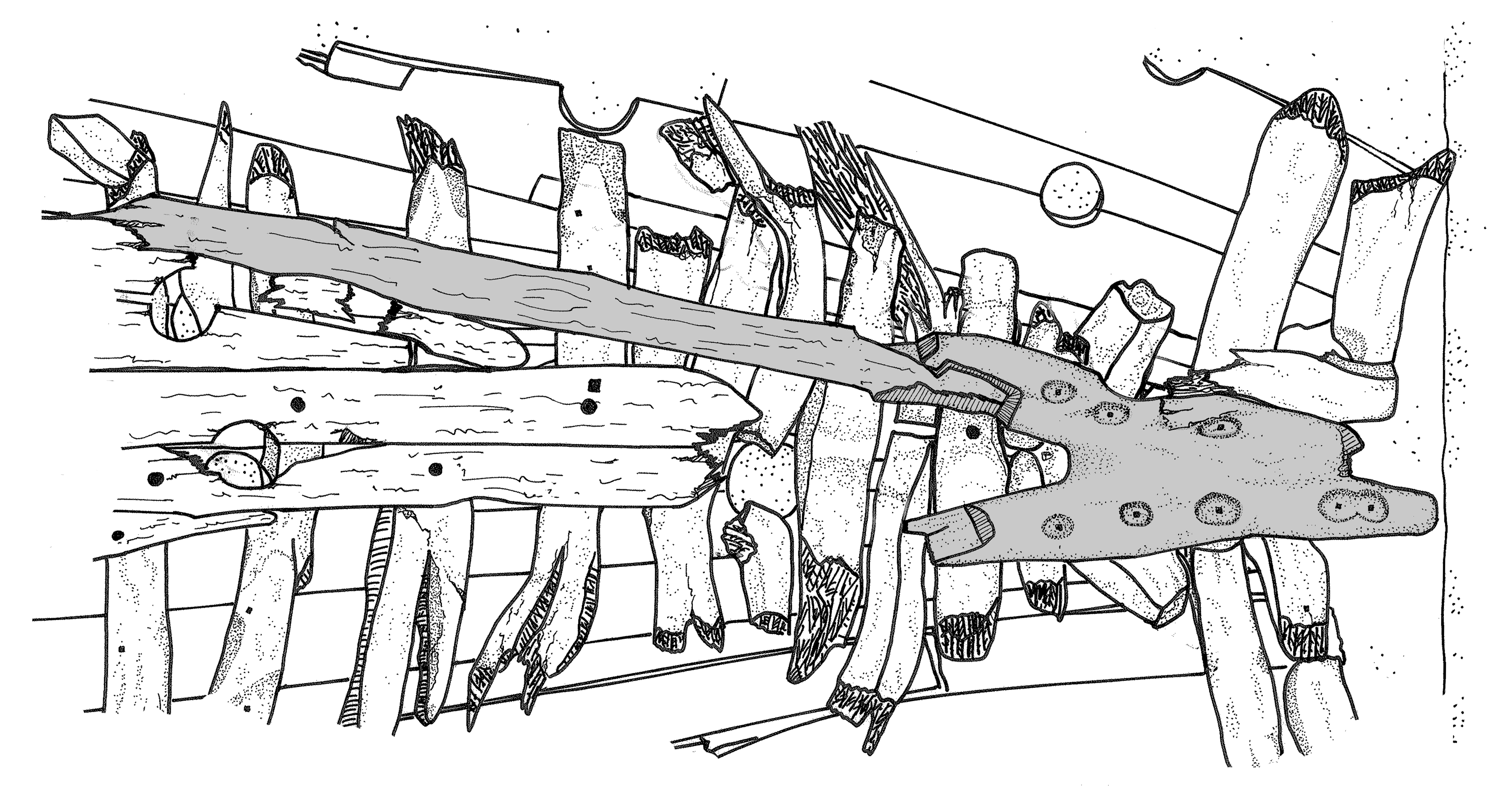
Stringers
Two stringers ran along the bottom of the ship, along the turn of the bilge, separated by pine ceiling planking, the only pine planks identified in the ship remains (Fig. 6). Only a small portion of the lower stringer survived in the northern portion of the hull, but both stringers survived in the southern section. The stringers were 18 cm sided and 17 cm molded and connected through horizontal hooked scarves about 60 cm long. According to Paulo Jorge’s notes, the stringers were spiked and bolted to the frames, with two spikes per frame, but the rhythm of the bolting is not indicated (Rodrigues 2002, 23).
Orlop Beam
One beam placed low in the hull can be seen in the total station site plan and in some of the pictures. It is concave and rests on a notch on the upper stringer. At this point, we have not been able to find a drawing of this timber.
Buttress and Pump Sump?
One timber, found lying (not fastened) over floor timber C98, was thought to be a buttress. Both the buttress and floor timber C98 were notched on their stern faces, C98 on both sides of the keel, with notches 5 cm deep and 25 cm wide, 40 cm to port side and 50 cm to starboard of the keel axis. A similar cut can be seen on a small rectangular ceiling board, which defined a rectangular hole 25 x 20 cm where a stanchion seems to have been placed. If this was the location of the main mast step, it is possible that these notches were related to the pump sump structure.
Stanchion
As mentioned above, a stanchion with a square section of 10 cm on a side was partially preserved along 54 cm, still inserted on a mortise, over frame C144.
Whipstaff
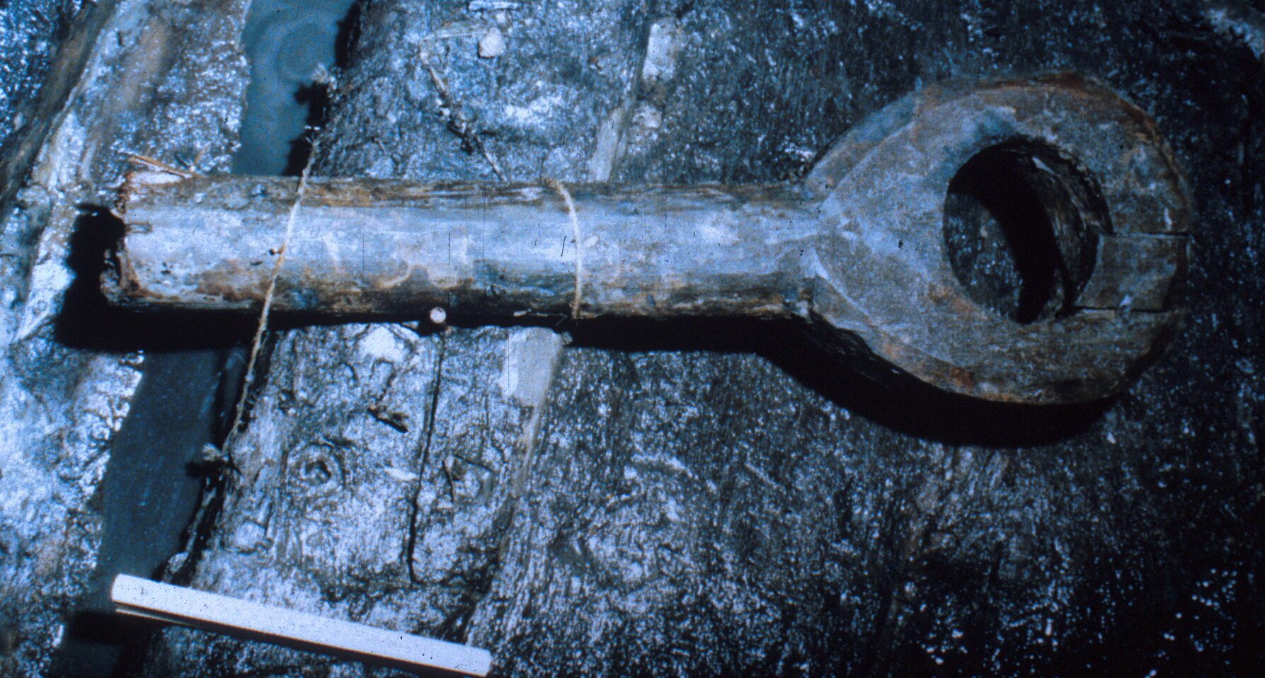
The lower portion of a whipstaff was found lying on the ceiling planking, over frame C88. It has not yet been recorded at a 1:1 scale. Cut from a hawthorn tree (Crataegus monogyna), it was preserved along 75 cm of its length, with a diameter of 8 cm. The lower ring is 28 cm in diameter and the hole is 14 cm. The thickness of the lower ring is also about 8 cm.
Cargo
There was no cargo associated with the hull.
Personal Items
There were no personal items, other than a show sole.
Rigging
As mentioned above, two blocks were found but not published.
Reconstruction
We have attempted several reconstructions of this hull. Because the scantlings seem to light for the length of keel, it looks like this is not an oceangoing merchantmen.
Deliverables
Publications
Castro, F., 2002. The Cais do Sodre Ship Frames – 2002 Field Season – ShipLab Report 4. on file in IPA/CNANS’ library, 2002, and in Nautical Archaeological Program Library, Texas A&M University.
Castro, F., 2001. Relatório dos trabalhos de registo arqueográfico das madeiras do navio do Cais do Sodré, Verão de 2001, on file in IPA/CNANS’ library.
Castro, F., and Yamafue, K., 2010. The Cais do Sodre Ship – ShipLab Report 13. on file in IGESPAR/DANS’ library, 2010, and in Nautical Archaeological Program Library, Texas A&M University.
Castro, F., Yamafune, K., Eginton, C., and Derryberry, T., 2011. “The Cais do Sodré Shipwreck,” in International Journal of Nautical Archaeology, 40.2: 328-343.
Rodrigues, P., 1995. Relatório Preliminar dos trabalhos de desobstrução e registo arqueográfico dos restos do navio encontrado no Cais do Sodré, nas obras do Metropolitano de Lisboa, Lisboa: I.P.P.A.R.
Rodrigues, P., 2002. Étude de la charpente transversale du navire de Cais do Sodré de la 2ème moitié du XVe siècle/début du XVIe, Thèse de Maîtrise, Université de Paris I – Sorbonne.
Rodrigues, P., Alves, F., Rieth, E., Castro, F., 2001. “L’épave d’un navire de la moitié du XV.ème siècle / début du XVI.ème, trouvée au Cais do Sodré (Lisbonne). Note Préliminaire”, in F. Alves (ed.) Proceedings of the International Symposium ‘Archaeology of Medieval and Modern Ships of Iberian-Atlantic Tradition’, Lisbon: Instituto Português de Arqueologia, : 347-380.